内容概要
The robot's load record must represent the complete supported tooling and the workpiece state, with every centre-of-gravity coordinate expressed in the required frame. Total mass alone cannot establish suitability; the integrator must also assess the applicable moment, inertia and robot operating limits.
Draw a boundary around the supported assembly
Start the load record at the robot's tool interface and list what the robot supports beyond it. Include adapters, tool-changer components, the gripper, custom fingers, brackets and attached instrumentation. Account for supported services using the robot manufacturer's guidance. Separate fixed tooling from the workpiece so an empty-tool record can be checked independently. Use a bill of materials with quantity, mass, evidence source and inclusion status. A row marked unknown is more useful than an omitted component that disappears from the calculation.
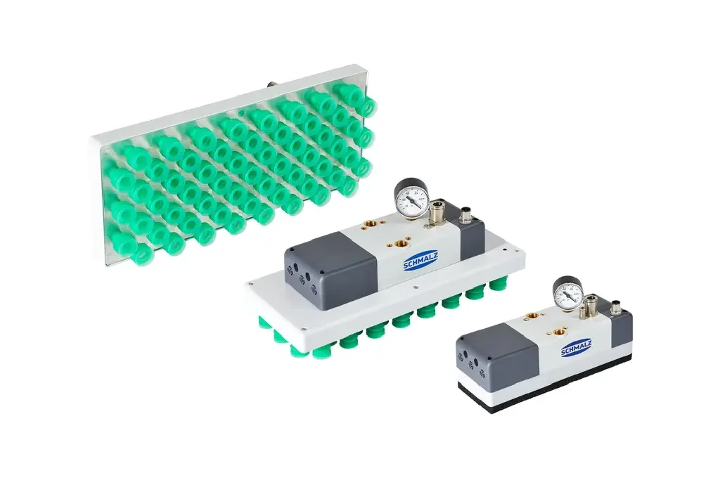
Check the boundary of every published figure. The Schmalz FQE reference table includes a UR flange, demonstrating why a catalogue total must be reconciled with the assembly before it enters your ledger. Do not both retain an included component and add it again as an accessory. Equally, do not assume a camera bracket is included because the camera appears in a promotional image. Ask the supplier for a written inclusion statement when a figure cannot be unambiguously matched to the drawing.
参考资料: FQE operating instructions: reference mass and centre-of-gravity table, page 19
Keep the positioning point separate from the load point
The tool centre point defines the point used for positioning the tool; the centre of gravity describes the distribution of its supported mass. They can occupy different locations and should be documented separately. Fairino's documentation provides separate tool-coordinate and end-load settings. For a suction assembly, for example, the useful positioning point might be associated with the contact surface, while the vacuum generator and adapter place much of the mass elsewhere. A correct pickup position therefore does not validate the load record.
Ask for a coordinate sketch showing origin, axis directions and units beside the component ledger. Require each supplier's centre-of-gravity data to identify its reference frame. If a component is rotated or displaced in the assembly, the integrator must transform its coordinates before combining them. A number labelled Z without its origin is incomplete data. Preserve the drawing and transformation assumptions so a later adapter change can be traced to the affected load entries.
Combine centres using a mass-weighted average
For components in the same coordinate frame, calculate each combined coordinate by multiplying every component's mass by that coordinate, summing the products and dividing by total mass. NASA's centre-of-gravity explanation gives this mass-weighted relationship. Apply it independently to the relevant axes. This arithmetic describes where the combined mass acts; it does not produce an allowable payload, a dynamic assessment or permission to run a robot. Those questions still require the manufacturer's limits and qualified integration review.
Give each calculation input a component identifier and drawing revision, retain units in column headings and distinguish measured values from estimates. Before accepting a result, check that the combined point lies within the range of the component centres along each axis for positive component masses. An unexpected point outside that range suggests an input, sign or formula problem.
Worked hypothetical example: empty and carrying states
The following figures are invented only to demonstrate bookkeeping, not specifications for any product. Assume a rigid assembly with all component centres on the same positive Z axis. The empty tool contains an adapter of 0.30 kg at 20 mm, a gripper of 0.80 kg at 80 mm and a sensor assembly of 0.10 kg at 120 mm. Its total mass is 1.20 kg. Its Z numerator is 0.30 x 20 + 0.80 x 80 + 0.10 x 120 = 82 kg mm, giving approximately 68.3 mm.
Add a hypothetical 0.60 kg workpiece centred at 180 mm. The carrying state becomes 1.80 kg, with Z equal to (82 + 0.60 x 180) / 1.80, approximately 105.6 mm. The shift matters even though the tooling has not changed. These assumptions omit moving internals and flexible services, and neither result is an approved controller setting. In a real project, replace every invented input with evidence and have the resulting states assessed for the specific robot and motion.
Review moments and inertia beyond the mass total
ATI's tool-changer selection guidance emphasises moment capacity and the position of the end effector's centre of gravity. Universal Robots separately documents payload inertia as part of its load configuration. These sources expose different checks: the robot's load model and the coupling's mechanical capacity both matter. A total mass below a nominal payload label is therefore only an initial screen. Request the robot and tooling assessments for the actual arrangement, including the effects of the intended movement and stopping behaviour.
When considering a longer adapter, ask which requirements it solves and which assessments it changes. It might improve access while moving the gripper and workpiece farther from an interface. Compare alternative layouts before committing to the extension. Give the integrator the assembled geometry, workpiece states and proposed task rather than a single mass number. Where inertia data are needed, obtain an appropriate model or manufacturer-supported identification result; do not replace a complex assembly with an unexplained default and assume equivalence.
参考资料: Robotic Tool Changer Selection · Payload, PolyScope 5.22
Check units and the exact controller documentation
Fairino's cited SDK documentation specifies kilograms for end-load weight and millimetres for centre-of-mass coordinates. The cited Universal Robots set_payload reference expresses its centre-of-gravity displacement in metres. This is a concrete reason to keep units attached to data exported between tools. A drawing value should never move into a controller field merely because both use the same axis letter. Match the manual and integration method to the actual controller version before implementing any load-setting procedure.
Use the handover review to trace a single coordinate from the component drawing through the combined calculation into the intended controller record. Check units, reference frame, axis signs and selected load identity along the way. Keep this review separate from editing the running system. The old or example commands in documentation are evidence of parameter meaning, not instructions to paste into a live robot. Qualified personnel should use the supported procedure, verify the active state and retain a recoverable configuration record.
参考资料: Common Robot Settings, FAIRINO manual 3.8.0 · URScript set_payload(m, cog), SW10.12
Verify the states the programme will actually use
Universal Robots documents multiple payload definitions and switching between them during pick-and-place work. Use that concept to review your process states without assuming every controller implements them identically. List what the robot carries at startup, after a successful pickup, after release and after a tool exchange. Include an interrupted cycle in the review. The integrator needs a reliable basis for choosing the active load, especially when the physical part state may be uncertain after a fault.
Reconcile calculated data with the finished assembly during commissioning. Manufacturer-supported identification can help, but it must be performed using its prescribed conditions and a controlled workspace. Fairino warns that incorrect load settings can affect drag-mode behaviour. Do not attempt to compensate for an uncertain mass by adjusting protective functions. Resolve discrepancies between drawings, measurements and identification results, and record which evidence the integrator accepted. The aim is a consistent explanation of the physical state, rather than a setting that merely suppresses an inconvenient symptom.
参考资料: Payload, PolyScope 5.22 · Common Robot Settings, FAIRINO manual 3.8.0
Keep load data attached to change control
Treat a tool modification as a question about the existing load record. Replacement fingers, a new camera mount, a longer coupling or a different workpiece can change the inputs even when the robot programme looks familiar. Robotiq's Hand-E specifications distinguish mounting arrangements in its centre-of-mass information, reinforcing the importance of configuration. Give the tooling assembly a revision identity and connect it to the relevant drawings, controller records and application assessment. Keep superseded records available for diagnosis but clearly distinguish the accepted configuration.
At handover, identify who may approve a replacement as equivalent and what evidence that decision requires. Include the mass ledger, coordinate sketch, calculation assumptions and empty versus carrying states in the maintenance information. In a private experimental workshop, a concise record is still worthwhile: it prevents next month's investigation from starting with unexplained values. The record should answer what is mounted, what is carried, where the data came from and which qualified review established the operating scope.
参考资料: Hand-E instruction manual: Specifications and centre of mass
检查清单
- List the complete supported assembly without omissions or double counting.
- Label the coordinate origin, axes and units.
- Separate TCP data from centre-of-gravity data.
- Calculate empty and carrying states from traceable inputs.
- Obtain the required robot, moment and inertia assessments.
- Match configuration procedures to the installed controller version.
- Reconcile the finished tool with its approved load records.
- Review load data whenever the assembly or workpiece changes.
常见问题
Is the workpiece weight the robot payload setting?
Not by itself. The relevant supported tooling must also be represented, and the carrying state can have a different centre of gravity from the empty tool. Confirm the exact configuration procedure with the robot documentation.
参考资料: Payload, PolyScope 5.22 · Common Robot Settings, FAIRINO manual 3.8.0
Can the same centre-of-gravity numbers be copied between robot brands?
Only after verifying units, origin and axis conventions. The cited Fairino SDK uses millimetres for these coordinates, while the cited URScript reference uses metres for displacement from the tool mount.
参考资料: Common Robot Settings, FAIRINO manual 3.8.0 · URScript set_payload(m, cog), SW10.12
来源与审核
Documentary guidance, not a physical load-identification test or robot capacity assessment. The worked example uses hypothetical inputs. The deprecated set_payload reference is cited only to illustrate units, not as an implementation recommendation.
适合读者:Tool designers and robot owners. 更新于 .
- FQE operating instructions: reference mass and centre-of-gravity table, page 19
- Common Robot Settings, FAIRINO manual 3.8.0
- Aircraft Center of Gravity
- Robotic Tool Changer Selection
- Payload, PolyScope 5.22
- URScript set_payload(m, cog), SW10.12
- Hand-E instruction manual: Specifications and centre of mass