In brief
Budget the complete assembly carried by the FR5, including tooling and workpiece, and review its mass distribution as well as its total weight. The nominal payload is a starting point; obtain confirmation for the actual load geometry, motion and operating configuration before approving the application.
Establish a payload ledger before buying tooling
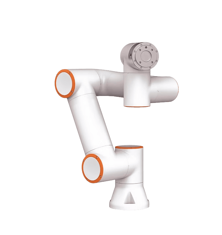
FAIRINO's FR5 page lists a nominal payload of 5 kg. Build your buying worksheet around the complete carried package rather than treating that figure as an allowance for the component alone. The ledger should identify each item, its mass, where it sits, the source of that information and whether the value is measured or provisional. Give every provisional entry an owner and a date for confirmation.
Include easily overlooked accessories such as finger fasteners, an adapter plate, a camera bracket and the portion of services carried with the tool. Ask the integrator how it will account for external cable or hose forces; those are not resolved by adding a guessed mass to the spreadsheet. The practical objective is a traceable assembly definition that a supplier can review, with enough detail to reveal what changes when a component or accessory is substituted.
References: FR5 product specifications · User Manual 3.8.3: Installation, load curves and centre-of-gravity offset
Separate supplier values from assembled measurements
A catalogue value may describe the gripper body without your fingers or mounting hardware. Ask vendors to state the boundary of every quoted mass and to supply a drawing or model with the relevant reference frame. Once the assembly exists, arrange a suitable measurement and reconcile it against the ledger. Preserve both values with an explanation for any difference, rather than silently replacing the estimate and losing the reason the budget changed.
FAIRINO's Base chapter provides fields for end-load mass and centre-of-mass coordinates. Your ledger should make those inputs auditable, while leaving configuration to the qualified integrator. Add a notes field for cables, moving jaws and unusual accessories. A convincing worksheet does not need many decimal places: it needs consistent units, identifiable components and a clear route from purchased equipment to the load definition used in the commissioned program.
References: User Manual 3.8.3: Base, payload and coordinates
Work a hypothetical mass budget
The following numbers are invented planning inputs, not specifications for any commercial gripper or approved FR5 application. Suppose the assembly contains a 1.30 kg gripper, 0.35 kg of custom fingers, a 0.25 kg adapter, 0.15 kg of attached accessories and a 1.80 kg workpiece. Its estimated carried mass is 3.85 kg. The arithmetic difference from the FR5 nominal figure is 1.15 kg; that difference is not automatically usable capacity.
Record what remains unknown before celebrating the subtraction. Perhaps the final finger material is undecided, the tool changer has not been selected or the parts arrive with retained material. Give each uncertainty a concrete resolution step, such as weighing the completed fingers or obtaining the heaviest representative part. Avoid a universal percentage reserve presented as a manufacturer rule. Your buying decision should be based on the completed package and its reviewed operating envelope.
| Hypothetical item | Estimated mass |
|---|---|
| Gripper body | 1.30 kg |
| Custom fingers | 0.35 kg |
| Adapter | 0.25 kg |
| Attached accessories | 0.15 kg |
| Workpiece | 1.80 kg |
| Total | 3.85 kg |
References: FR5 product specifications
Make mass distribution visible
A payload ledger needs geometry because an offset load is different from the same mass concentrated close to the flange. FAIRINO's installation chapter explicitly relates rated payload to centre-of-gravity offset. Ask the tool designer for the assembled centre of mass in a named coordinate frame, including the workpiece in its actual grasp position. Do not confuse the tool centre point, which describes a working reference, with the assembly's centre of mass.
Hypothetical arithmetic illustration: a 2 kg tool assembly centred 60 mm along a chosen axis and a 1 kg part centred 180 mm along that same axis have a combined coordinate of 100 mm: (2 times 60 plus 1 times 180) divided by 3. These assumed positions share one frame. This static calculation illustrates mass weighting only; it does not evaluate inertia, contact forces, cable loading or dynamic suitability. Ask the integrator to assess those separately.
References: User Manual 3.8.3: Installation, load curves and centre-of-gravity offset · User Manual 3.8.3: Base, payload and coordinates
Define every carried state in the cycle
Describe the load when the tool is empty, when a part is held, when a second item is present and when the process changes the workpiece. A fixture transfer can also create a period when support is shared. Have the application designer identify those states and decide how the control program represents them. Do not assume a single entry made during setup describes the whole process accurately.
The Common Settings SDK chapter documents load weight and centre-of-gravity setters and corresponding getters. This supports a useful purchasing question: how will the integrator demonstrate that the expected load data are active at each relevant transition? Request a reviewed state table and commissioning evidence, not an improvised instruction to change settings during production. If the tool handles variable products, define the permitted recipe set and the response when a product cannot be identified reliably.
References: C++ SDK: Common Settings, load weight and centre of gravity
Review the tool as an interface, not just a weight
Ask the tooling vendor to describe the complete delivered configuration: device model, finger drawing, adapter arrangement, services and feedback used to establish a valid grip. FAIRINO's peripheral documentation distinguishes gripper manufacturer, type, software version and mounting location. A familiar gripper name in a quotation therefore leaves important details unresolved. Assign responsibility for checking electrical compatibility, service routing and the integration method against the exact controller and end interface being supplied.
For a hypothetical part transfer, define what evidence allows the robot to leave the pickup station. A command to close the gripper is not itself proof that the correct part is secured. Ask the integrator to propose appropriate confirmation and a controlled response when confirmation is absent. This question also affects the payload definition: the program should not proceed on the assumption of a known carried state when the application has failed to establish it.
References: User Manual 3.8.3: Peripheral and gripper configuration
Turn a budget shortfall into design options
When the review identifies a problem, ask for alternatives that address its cause. These might include a lighter adapter, shorter fingers, a different grasp, a relocated fixture or another robot model. Compare each alternative against access, grip reliability, maintenance and application performance. A lighter component can create another cost if it is harder to replace or requires a more complicated fixture to present the part consistently.
Keep an option table showing the changed component, expected benefit, new uncertainty and required test. Avoid treating a higher listed maximum as a purchasing shortcut. The load-curve documentation distinguishes operating conditions, so any proposal that depends on an extended operating envelope needs explicit supplier review. Do not alter collision protection or other safeguards to make a payload demonstration pass. A failed qualification should lead to a revised design or a clearly documented application limitation.
References: User Manual 3.8.3: Installation, load curves and centre-of-gravity offset
Freeze and maintain the approved assembly definition
Close the tooling purchase with a revision-controlled ledger, assembled drawing, measured values and the integrator's qualification record. Link those records to the program and recipe identifiers used in the acceptance demonstration. Include photographs that make the tested assembly recognisable. The goal is to let a later maintainer determine whether the equipment in front of them is still the equipment that was reviewed, without reconstructing the project from supplier emails.
Define changes that trigger another review: new fingers, a longer bracket, a replacement gripper, an added sensor or a different part family. Ask for load-setting verification within the handover procedure and record who may approve revisions. Keeping the budget current is a practical buying discipline, not a one-off spreadsheet exercise. The strongest evidence is a consistent chain from the physical assembly, through its documented load states, to the configuration and motion that were actually qualified.
References: User Manual 3.8.3: Base, payload and coordinates · C++ SDK: Common Settings, load weight and centre of gravity
Checklist
- List every component in the carried assembly.
- Mark masses and geometry as measured or provisional.
- Use consistent units and a named reference frame.
- Document empty, loaded and variable-product states.
- Obtain application-specific load qualification.
- Confirm grip feedback and interface responsibilities.
- Link the accepted assembly revision to the commissioned program.
Common questions
Does a positive mass remainder prove that another sensor can be added?
No. Recalculate the assembled mass distribution and ask the integrator to review the revised geometry and motion. A subtraction from nominal payload does not establish the remaining permitted operating envelope.
References: User Manual 3.8.3: Installation, load curves and centre-of-gravity offset
Can automatic load identification replace the tooling ledger?
The Base manual describes an identification function, but the ledger still explains what was installed and which load state was measured. Any identification movement and use of its result belong in a qualified commissioning procedure.
References: User Manual 3.8.3: Base, payload and coordinates
Sources & review
Documentary tooling-budget guidance prepared for 5 September 2026, not a load test or approved application. All worked masses and offsets are hypothetical. Official references establish product and configuration facts; the ledger and review workflow are original editorial recommendations.
Audience: Tooling and project buyers. Updated .
- FR5 product specifications
- User Manual 3.8.3: Installation, load curves and centre-of-gravity offset
- User Manual 3.8.3: Base, payload and coordinates
- C++ SDK: Common Settings, load weight and centre of gravity
- User Manual 3.8.3: Peripheral and gripper configuration