In brief
Use the FR3 reach specification to screen a layout, then check every required tool pose and the complete motion between poses. A workable station also needs space for the arm, tool, services, replenishment and qualified safeguarding, so approve a documented layout rather than a reach circle.
Treat reach as a screening fact
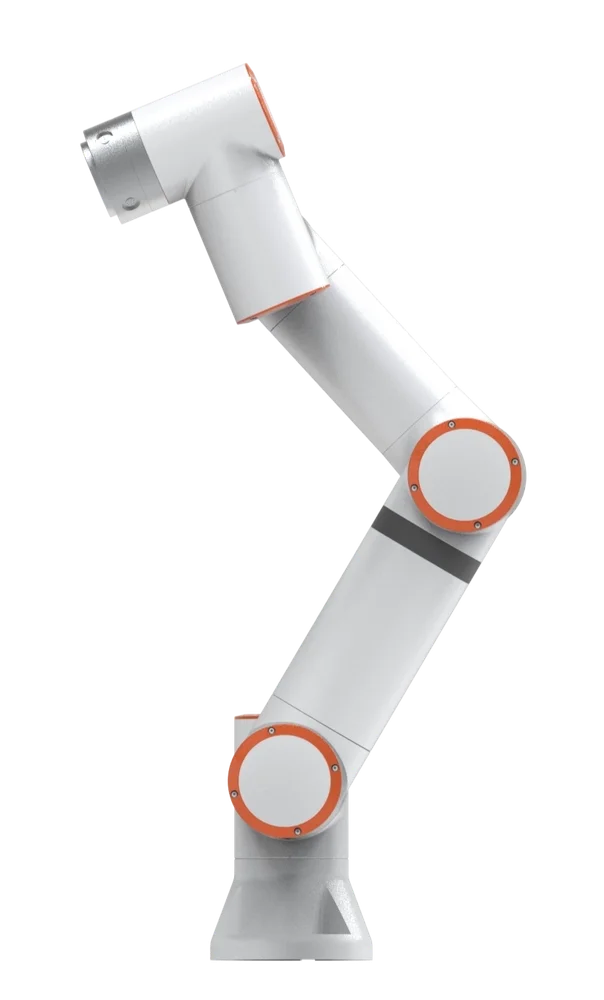
FAIRINO lists 622 mm reach for the FR3. That fact helps identify layouts worth investigating, but it does not describe all possible tool orientations or a guaranteed clear route to a fixture. Put the exact model and variant on the layout drawing before starting. Similar model names should not be treated as interchangeable geometry, especially when the project relies on a particular approach around the base or through a narrow opening.
Start with the process surfaces: where the part is presented, where it must be processed and where acceptable output is placed. Identify the surfaces that are fixed and those that can move. This distinction often matters more than optimising the robot location immediately. A movable tray gives the integrator a design option; an existing machine opening may impose a constraint that the whole station must accommodate. Record both explicitly on the first layout revision.
References: FR3 product specifications · User Manual 3.8.3: Robot brief introduction and motion ranges
Create a register of required poses
For every process location, specify the intended working point, tool orientation, entry direction and withdrawal direction. Give each entry a plain name such as tray pickup, machine approach, seated part or reject drop. Add the expected loaded state and the fixture condition. This register turns a vague request to reach the machine into a set of questions that a robot supplier can answer and demonstrate individually.
FAIRINO's Base documentation treats tool and workpiece coordinates separately. Ask the integrator to map your register into clearly named frames and explain which physical features establish them. Keep the flange, tool centre point and workpiece datum distinct on drawings. A supplier should be able to explain how a longer finger or a shifted tray changes the required flange pose. The buyer need not calculate the robot's kinematics to demand that level of clarity.
References: User Manual 3.8.3: Base and coordinate systems
Work a hypothetical machine-opening problem
Imagine a station with a fixture centre 480 mm horizontally from the planned robot base reference and 200 mm above that reference. The straight-line distance between those assumed points is 520 mm. That arithmetic does not prove feasibility: the point describes a workpiece location, while the robot must place its flange so that the complete tool reaches it in the required orientation. These are hypothetical layout dimensions, not FAIRINO application limits.
Now suppose a machine lip requires the tool to approach from above and the part must remain upright on withdrawal. Add those conditions to the pose register and ask for a modelled approach and exit. A useful supplier response might relocate the base, revise the fixture or change the tool geometry. Compare those alternatives using the whole process, including the loaded withdrawal, rather than approving the endpoint because its distance seems comfortably inside the advertised reach.
References: FR3 product specifications · User Manual 3.8.3: Robot brief introduction and motion ranges · User Manual 3.8.3: Base and coordinate systems
Review swept volumes and service routing
Request drawings or model views showing the whole arm and tool along the proposed path. Include fingers in their relevant positions, the held workpiece and any protruding fittings. Review the fixture and machine in their actual operating states, such as an open door or released clamp. A single screenshot of a successful endpoint leaves too much hidden about what moves through the intervening space.
FAIRINO's teaching interface documentation includes virtual trajectory display and imported tool models. Those features can support a review, but ask what is actually represented and what has been omitted. Cable loops, flexible hoses and unusual workpiece features deserve their own review where they are absent from the model. Have the integrator document expected service routing and how it will be checked during commissioning. Simulation evidence should identify its assumptions as clearly as its successful poses.
References: User Manual 3.8.3: Teaching pendant software, virtual trajectories and tool models
Compare base and fixture options together
Prepare a small set of alternative layouts instead of continually nudging the robot in one unfinished drawing. One may favour the machine opening, another replenishment access and another a future inspection station. Compare each against the same pose register. Keep a reason for rejecting an option, such as obstructed maintenance access or an unresolved tool orientation, so that later discussions do not repeatedly reopen the same unsuitable arrangement.
Treat mounting as a structural and integration decision. Obtain the applicable mounting drawing and have qualified personnel assess the support, attachment and installation conditions. The manufacturer's installation chapter is the reference for that work; this guide does not supply fastening instructions. A pedestal is also part of the application geometry: changing its position or height affects the coordinates, service routing and motion that must be checked. Freeze the accepted arrangement before final teaching and acceptance measurements.
| Layout question | Evidence to compare |
|---|---|
| Machine access | Loaded approach and withdrawal views |
| Replenishment | Operator task and access arrangement |
| Tool services | Routing across the intended motion |
| Mounting | Reviewed base and support drawings |
| Maintenance | Access to fixtures and serviceable equipment |
References: User Manual 3.8.3: Robot brief introduction and motion ranges · User Manual 3.8.3: Installation specifications
Reserve space for the work people still perform
List the human tasks around the station: loading trays, replacing fingers, clearing rejected parts, inspecting output and servicing the machine. Give each task a location and an intended machine state. Ask whether a person can complete it with appropriate access after the robot and peripheral equipment are installed. This can reveal a layout that looks efficient in automatic operation but becomes difficult to replenish or maintain.
Ask the qualified integrator to develop and validate the protective arrangements for the complete cell. FAIRINO's Safety chapter documents emergency-stop, protective-stop and safety-plane configuration topics; their presence does not approve your layout or define the space a person needs. Do not infer a safe separation distance from an arm's reach figure. Request the assessment and validation evidence applicable to the actual tool, process and operator tasks, with clear responsibility for any changes discovered during the layout review.
References: User Manual 3.8.3: Safety configuration
Request a bounded feasibility demonstration
Select the poses and transitions that are hardest to establish from drawings. Ask a qualified demonstrator to reproduce those conditions using the intended tool or a documented representative assembly in an appropriately controlled setup. Include the highest and lowest relevant fixture locations, the constrained withdrawal and the return to pickup. Define which substitutions are acceptable before the demonstration so that a shortened tool or removed obstruction is not mistaken for a completed test.
Retain a result for each item in the pose register. Useful records include layout revision, tool definition, configuration identifiers, observations and unresolved restrictions. If a path succeeds only after the supplier moves the fixture, update the drawing and revisit the other required poses. A feasibility demonstration is a decision aid for the proposed geometry; it should not be described as production validation or used to justify unreviewed physical operation at the customer's site.
References: User Manual 3.8.3: Teaching pendant software, virtual trajectories and tool models · User Manual 3.8.3: Robot brief introduction and motion ranges
Deliver a layout that can be rechecked
The planning output should be a compact evidence package: dimensioned layout, pose register, tool model, fixture states, mounting proposal and the results of the feasibility review. Add a list of assumptions that remain outside the model. Give every item a revision so that a programmer, fixture supplier and safety specialist can tell whether they are reviewing the same station. Record which dimensions were measured on site and which came from preliminary supplier drawings.
Make change triggers explicit. A taller tray, longer finger, relocated base or new inspection fixture should prompt a review of the affected poses and transitions. Ask who maintains the coordinate and layout records after handover. This is what makes workspace planning useful beyond initial selection: the buyer can connect a proposed physical change to the exact evidence that needs updating, instead of assuming that a robot which once reached the job will accommodate every later revision.
References: User Manual 3.8.3: Base and coordinate systems · User Manual 3.8.3: Robot brief introduction and motion ranges
Checklist
- Identify the exact FR3 variant and geometry reference.
- Mark fixed and movable process locations.
- Register positions, orientations, approaches and exits.
- Include the complete tool, part and service routing.
- Review mounting and human access with qualified specialists.
- Demonstrate the limiting transitions under controlled conditions.
- Freeze layout revisions and define change-review triggers.
Common questions
Can I add tool length to the advertised reach?
Do not use that sum as proof of workspace coverage. Tool length changes the flange pose required for each working point, and the complete arm, orientation and path still need a geometry review.
References: User Manual 3.8.3: Robot brief introduction and motion ranges · User Manual 3.8.3: Base and coordinate systems
Is a virtual trajectory enough to approve the station?
It is useful evidence when its model and assumptions are known. The intended services, fixtures, human tasks and protective arrangements still require integration review and appropriate physical validation.
References: User Manual 3.8.3: Teaching pendant software, virtual trajectories and tool models · User Manual 3.8.3: Safety configuration
Sources & review
Documentary workspace-planning guidance prepared for 5 September 2026. No physical FR3 layout was tested. The numerical layout example is hypothetical, and the pose-register framework is editorial guidance for qualified integration review, not a safety approval.
Audience: Workstation and fixture planners. Updated .
- FR3 product specifications
- User Manual 3.8.3: Robot brief introduction and motion ranges
- User Manual 3.8.3: Base and coordinate systems
- User Manual 3.8.3: Teaching pendant software, virtual trajectories and tool models
- User Manual 3.8.3: Installation specifications
- User Manual 3.8.3: Safety configuration